I2CChip.com: I2C Bus Connectors & Cables
|
|
Our Pinout is based on Philips recommendations. Our I2C Bus connector used is a MICRO-MATCH by AMP. This connector is small, reliable, polarised, and cheap. We recommend that you use it in your designs.
Premade Cables and Connectors are available  . Contact us for larger quantities . Contact us for larger quantities
| # |
6 way |
4 way |
|
| 1 |
SDA |
SDA |
|
| 2 |
VDD |
VDD |
|
| 3 |
VSS |
VSS |
|
| 4 |
SCL |
SCL |
|
| 5 |
INT / CS |
|
Interrupt input (active low). Can be used as CS when being used for an SPI bus. |
| 6 |
VAUX |
|
Aux supply (eg 12V). Not connected |
Predictably no two people use the same connector, hell Philips change pinout every year or two. So we have collected pinout and connector info for various companies, whose products you might want to actually use. We have an adaptor board available to make it easy to use boards from different companies, so you can get your job done.
|
Micro-match 6pin Connectors & Cables
Our Pinout
Either 4 or 6 way can be used. 0.050" ribbon cable is used and the connectors can be daisy chained on the wire. Because of the keying arrangement used, the 6 pin plugs can be correctly plugged into 4 pin sockets, so a mixed system is quite practical. For longest runs or best speed, use a 4 wire cable if you aren't going to use INT. We don't specify the use of VAUX. If you use it for something other than +12 we recommend it has a resistor in series of sufficient value to protect it in the event that it is connected to +12
| # |
6 way |
4 way |
|
| 1 |
SDA |
SDA |
|
| 2 |
VDD |
VDD |
|
| 3 |
VSS |
VSS |
|
| 4 |
SCL |
SCL |
|
| 5 |
INT/CS |
|
Interrupt input (active low) for I2C.
ALERT for SMBUS
CS when being used for an SPI bus.
|
| 6 |
VAUX |
|
Aux supply (eg 12V). Not connected |
Connector Part Number and Suppliers
| type |
AMP(Tyco) |
Farnell |
RS |
|
| 6 way male-on-wire |
7-215083-6 |
149-068 |
|
|
| 6 pin female-on board |
7-215079-6 |
148-519 |
|
|
| 6 pin side-entry female-on board |
7-215460-6 |
148-696 |
|
|
| 6 pin SMT female-on board |
7-188275-6 |
378-4721 |
|
|
| 6 pin female-on board, locking latch |
338068-6-6 |
|
|
|
| 4 pin male-on-wire |
7-215083-4 |
149-032 |
|
|
| 4 pin female-on-board |
7-215079-4 |
148-507 |
|
|
| 4 pin side-entry female-on-board |
7-215460-4 |
148-684 |
|
|
| 4 pin SMT female-on-board |
7-188275-4 |
378-4710 |
|
|
If you can suggest other local small order suppliers for Tyco/Amp connectors in your country, (esp. in USA) please send us mail telling us.
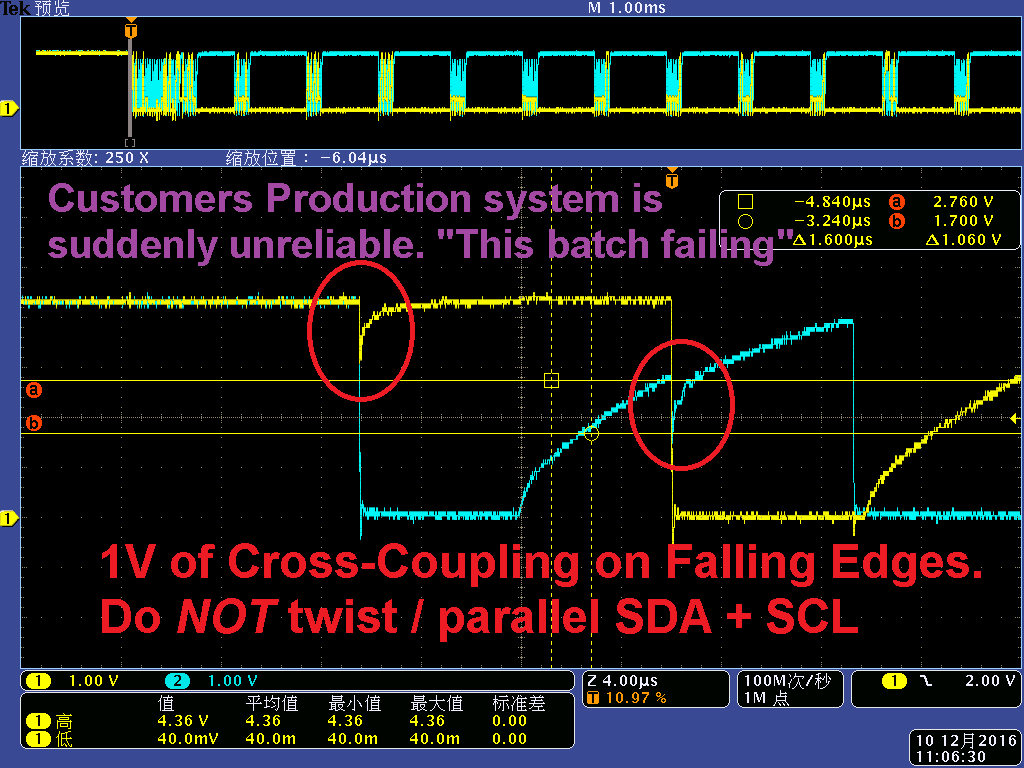
Crosstalk
Do NOT run SDA and SCL parallel, or twist them together. Yes, you got a module of Aliexpress in China that does this, but don't.
The reason for our arrangement of the power lines being between the I2C wires is to stop crosstalk. ie the edges of SDA and SCL coupling together. Placing VDD and GND between SDA and SCL, means that the capacitance on either signal line is equal (for 4 wire cable)
This is the Philips recommendation. The pattern is that set out in section 17.3 of The I2C Bus Specification. (there are recommendations for twisted pair etc)
- If the length of the bus lines exceeds 10 cm (ribbon cable or on pcbs)
- This arrangement will have similar capactive loading on SDA and SCL.
- Where you don't use pins 5 & 6, it can be better to just use 4 wires. For longer runs, use twist&flat ribbon, or split 5&6 from 1-4
- avoid bundled cable where the conductors aren't individually twisted pairs or individually screened
- VDD and GND are bypassed at both ends of the cable with 100nF capacitors.
Bus Pullups and Drive
The I2C Bus normally uses a resistive pullup. The exponential RC pullup characteristic slows the bus down and reduces the noise margin. Using a constant current pullup will improve this.
- Use a current mirror. Our Constant Current Pullup board does this
- Use a resistor to a higher voltage and a clamping diode to VDD (schottky)
- Use a bus buffer
Note that the I2C spec is for 1.5mA pullup current, and all chips will do this. Many have significantly greater capability, so you can run some busses at higher current. (eg our BL232 is happy at 15mA.
Bus Length
The length of the bus is limited by 3 factors
- Capacitance (time constant) and bit rate
- noise, RF, interference
- ground bounce etc
First see the Philips documents for info on bus speed and capacitance.
The basic limit for standard mode (100kHz) is 400pF. This is about 8m of 4 way ribbon cable (normally 40-50pF/m). Some STP (shielded-twisted-pair) cables have about 55pF/m, others have twice this. You can always reduce the bit rate to increase the bus length.
Noise, RF, and mains spikes set another limit. Frankly you would be insane to run 8m of ribbon cable. Every cellphone for about 100m would stop it working.
- Use plain ribbon cable for short runs only (eg <0.5m)
- use twist+flat ribbon for longer runs (it is normally at 0.5m pitch) or if there are high current spikes etc withing your system.
- Use screened and twisted cable for runs between boxes (STP). DON'T twist SDA and SCL together. Look at our bus, and either pair them with gnd, or pair SDA+VDD and SCL+GND
- Use 5V not 3.3V devices. Use I2C devices (CMOS schmitt trigger levels, not SMBUS devices (TTL levels, low noise margin)
- Run the bus at higher currents than 1.5mA - many I2C slaves can pull down higher currents.
- Don't run the bus fast if you don't need to.
- Use ferrite beads on all lines to suppress RF. We do. Add extra filtering when the bit rate is low.
Ground Bounce is a third problem. As the bus is single ended, any voltage drop and noise on the GND (and VDD) wires affects the threshold. For longer runs, or where modules draw a significant, and particularly, a fluctuating current, you must provide separate power wires for the high current circuits, and use the bus power to run the i2c interface chips. Large currentSome possible solutions are:
- Ensure adequate powersupply bypassing at ALL modules. This means real electrolytic capacitors.
- run bus at higher voltage. The 82B715 and 82B96 buffers allow a +12V bus, and higher currents.
- Use differential bus drive for really difficult environments.
- Use a galvanic isolator
How Do I2CChip Boards Help?
- I2C-2-PC can has high output drive. You can reduce pullup resistors as low as 330 ohm. You may need a buffer at the slave end as the I2C spec is for 1.5mA
- It has 3 busses, reducing the load on each bus.
- You can use one bus for long runs, and set the bit rate slow for just that segment. Leave the close runs at high speed
- I2C-2-PC is able to have one split bus for easy galvanic isolation.
- Put I2C-2-PC close to the I2C modules, and let the RS232 side take the long run. We have Fibre and Wifi options too.
- Constant Current Pullup speeds up bus.
- Buffer boards
- Differential bus board.
Some pinouts used by others. It seems no one uses the same pinout, even Philips change it every year...
So we have a Connector Adaptor Board for the common formats below
On the 2002 demo board, this is the layout used for the 0.1" headers. Some of our boards have holes for this header. Philips change this all the time...
These use loose cable rather than ribbon, and this kind of connector is far larger than the micromatch.
Another 0.1" connector
| # |
Name |
Desc |
| 1 |
SDA |
|
| 2 |
GND |
|
| 3 |
SCL |
|
| 4 |
+5 |
|
| 5 |
_RESET |
active low reset |
MCC used what was probably the only standard I2C connector: The ACCESS Bus connector from Molex. Unfortunately USB killed Access Bus. This must cast some doubt over the availability of this connector in future.
MCC/ACCESS BUS mod-type cable connector (This is on our adaptor Board)
iPack Stackable Board Format
Pond Electronics use an RJ45 connector, and a buffered I2C bus. They use the 82B715 buffer to increase bus current 10x, (15mA). In an email Paul claims "we have sucessfully run and powered our LCD down 250m of cable".
 (pdf)
(pdf)
| # |
Name |
Desc. |
| 1 |
gnd |
|
| 2 |
+12 |
|
| 3 |
gnd |
|
| 4 |
XSCL |
Buffered SCL |
| 5 |
gnd |
|
| 6 |
XSDA |
Buffered SDA |
| 7 |
gnd |
|
| 8 |
+12 |
|
Note that the I2C-2-PC has an 82B715 built in, so it can drive this bus directly. (This feature may be revised, so check with us before using)
To connect Connii or Audrii you will need a male Mini-DIN connector / cable as used for PS2 keyboard/mice.
male Mini-DIN connector |
| pin |
color |
signal |
| 1 |
black |
SDA |
| 2 |
brown |
reserved |
| 3 |
red |
GND |
| 4 |
orange |
VCC |
| 5 |
yellow |
SCL |
| 6 |
green |
reserved |
|
sales@i2cchip.com
http://www.i2cchip.com
Phone +64 21 623-402
Please send us mail telling us what you think about this page and how we might improve it.